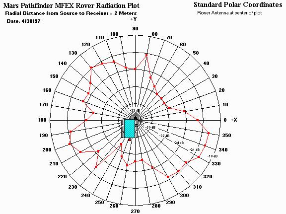
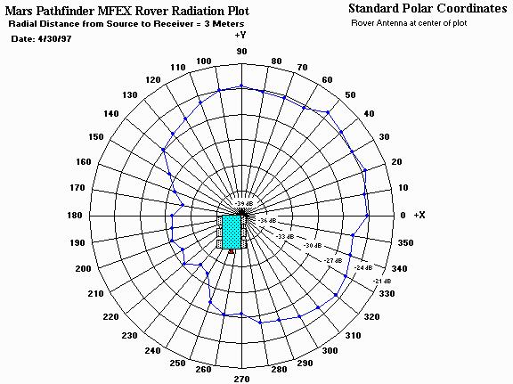
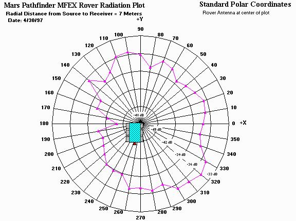
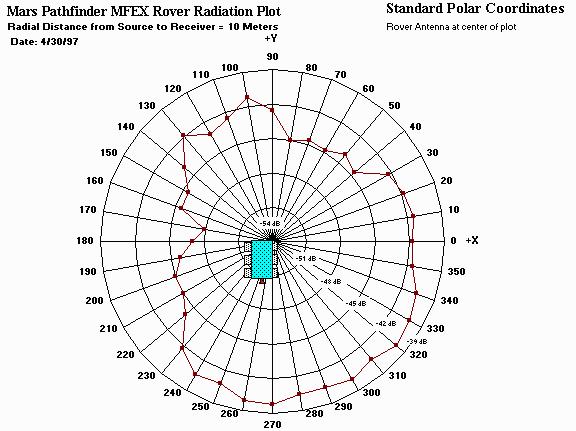
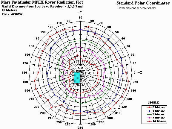
Rover Antenna Patterns
These patterns were taken on the JPL MESA antenna range using a static model rover. A flight-like rover antenna was mounted to the rover mast and placed a height of 83 cm from the ground. A radio modem operating in CW mode was used to transmit a 459.7 MHz, 100 mW signal from the rover to a spectrum analyzer receiver. The receive antenna was a flight-like LMRE antenna mounted to the receiver at a height of 80 cm.
Antenna Pattern at 2 Meters
Antenna Pattern at 3 Meters
Antenna Pattern at 5 Meters
Antenna Pattern at 7 Meters
Antenna Pattern at 10 Meters
Antenna Patterns from 2-10 Meters