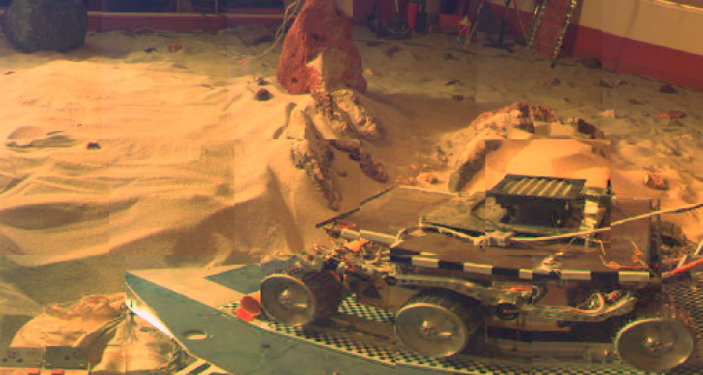
This first mosaic from the Mars Pathfinder was taken at 9 A.M. in the martian morning after the spacecraft landed today at the mouth of an ancient flood channel. The morning sun was to the left in this view. The mosaic shows the Sojourner rover prior to its leaving the lander. The rover wheels are about 5.5 inches in diameter. Two large rocks of markedly different color (upper left corner and upper center of the image), and nearby rocks, appear draped by reddish windblown sand. Magnets to measure the amount of magnetic dust can be seen in the lower left corner of the mosaic. (Click on the thumbnail image shown above to view the panorama in greater detail.)
The Sun as it would be seen from the surface of Mars (Sol 1).
By simply taking an image of the Sun using IMP, we can get a quick determination of the amount of dust in the atmosphere of Mars. By comparing the brightness of the Sun in this image to what it would be without any atmospheric opacity, we can calculate the optical depth, an important measure of how much of the incoming solar energy is absorbed by the Martian atmosphere. This calculation has a very real significance to the Mars Pathfinder mission, since the spacecraft is powered by solar panels, and more dust means less power. (The Sun in this 30 x 30 pixel image appears 38% smaller in diameter than it does from Earth.)

This is a panorama of the first set of images returned by the Mars Pathfinder
engineering model during ORT 6. The purpose of the mosaic is to assess the
position of the deflated airbags at the base of the lander. Determining
this is of crucial importance for judging whether or not the rover can safely
traverse off the lander on to the Martian surface. The images were taken
at a wavelength of 965 nanometers, (in the near infrared part of the electromagnetic
spectrum). The numbers on the images are frame IDs. The coordinate system,
shown by the white squares, is in degrees of elevation (vertical) and azimuth
(horizontal). There are no airbags visible, indicating that they have been
safely retracted. Note that there are two images labeled "1".
Image #1 at an azimuth of 320-335 degrees was taken through the right camera.
All other frames were imaged through the left camera. Parts of the lander
can be seen in the foreground. A radiometric calibration target is visible
in frames 7 and 8 and the solar panels are seen in the other images. The
undeployed atmospheric science/meteorology mast (ASI/MET) with wind socks
is visible in frames 1R, 9, and 10. The walls of the test bed can be seen
in several frames, as can other unnatural objects such as cords and possibly
a tripod (frame 1L). Many rocks and sand dunes are visible between the lander
and test bed walls, simulating the type of terrain that will probably be
seen on Mars. (Click on the thumbnail image shown above to view the panorama
in greater detail.)
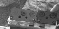
Image showing the lower of the two Magnet Arrays mounted on the Mars Pathfinder Lander. The Magnet Arrays are magnesium blocks with five embedded magnets of different strengths. These magnets will collect iron minerals from the airborne dust in the Martian atmosphere. A preliminary interpretation of the above image indicates the presence of an iron mineral, with a magnetization per mass greater than 50 Am2/kg, probably magnetite or maghemite.
The Pathfinder lander is equipped with two deployment ramps for use by the Sojourner Rover. The ramps are initially rolled up in a stowed configuration. Images acquired during Sol1 are analyzed to determine the rover deployment path that will present the least risk to the rover. A command is sent to the Pathfinder lander to deploy the selected rover ramp. Two thin metal strips made of spring steel snap into a tubular configuration as they rapidly unfurl the rover ramp. The two metal tubes can be seen in the above picture near the lower inner side of the rover wheels. They have the additional function of forming a track to help guide the rover down the deployment ramp.